
| product brand name | SINOVA | |
| product designation | Power contactor | |
| General technical data | ||
| size of contactor | 0 | |
| product extension auxiliary switch | Yes | |
| power loss [W] for rated value of the current at AC in hot operating state | 7.5 W | |
| ● per pole | 2.5 W | |
| insulation voltage | ||
| ● of main circuit with degree of pollution 3 rated value | 1 000 V | |
| ● of auxiliary circuit with degree of pollution 3 rated value | 1 000 V | |
| surge voltage resistance | ||
| ● of main circuit rated value | 6 kV | |
| ● of auxiliary circuit rated value | 6 kV | |
| protection class IP | ||
| ● on the front | IP20 | |
| mechanical service life (operating cycles) | ||
| ● of contactor typical | 10 000 000 | |
| reference code according to IEC 81346-2 | Q | |
| Substance Prohibitance (Date) | 07/01/2022 | |
| Weight | 0.354 kg | |
| Ambient conditions | ||
| installation altitude at height above sea level maximum | 2 000 m | |
| ambient temperature | ||
| ● during operation | -5 ... +55 °C | |
| ● during storage | -25 ... +70 °C | |
| relative humidity minimum | 10 % | |
| relative humidity at 55 °C according to IEC 60068-2-30 maximum | 95 % | |
| Main circuit | ||
| number of poles for main current circuit | 3 | |
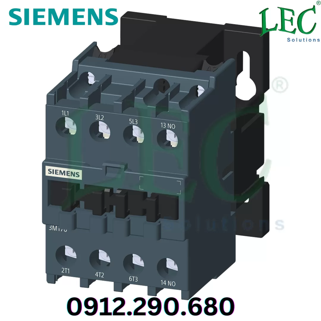
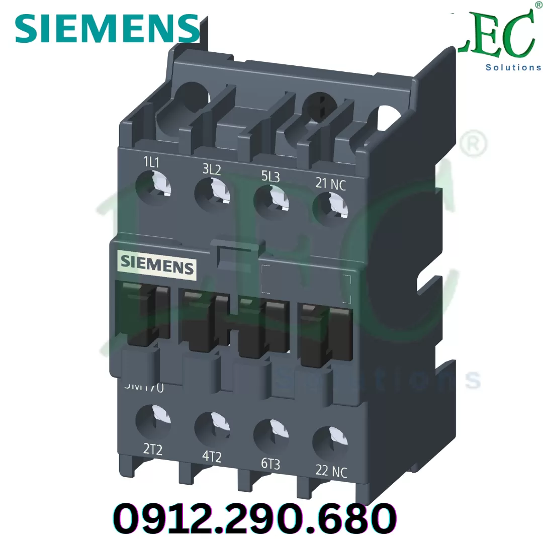
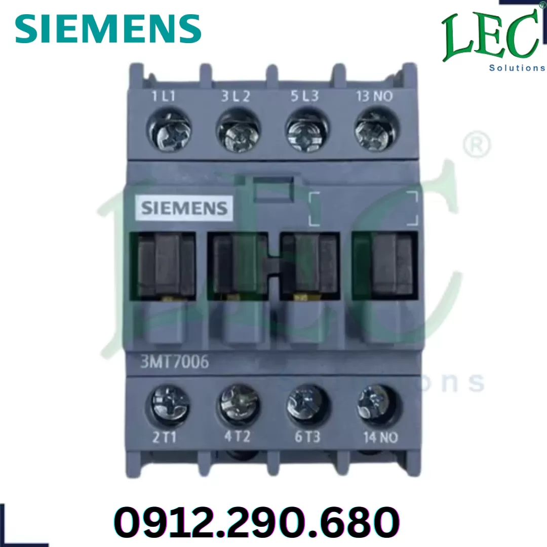
| number of NO contacts for main contacts | 3 | |
| operating voltage at AC-3 rated value maximum | 690 V | |
| operational current | ||
| ● at AC-1 at 400 V at ambient temperature 40 °C rated value | 25 A | |
| ● at AC-1 up to 690 V | ||
| — at ambient temperature 40 °C rated value | 25 A | |
| — at ambient temperature 60 °C rated value | 19 A | |
| ● at AC-3 | ||
| — at 400 V rated value | 6 A | |
| — at 690 V rated value | 4 A | |
| operating power | ||
| ● at AC-3 | ||
| — at 400 V rated value | 2.2 kW | |
| — at 690 V rated value | 3 kW | |
| no-load switching frequency | ||
| ● at AC | 1 800 1/h | |
| operating frequency | ||
| ● at AC-1 maximum | 600 1/h | |
| ● at AC-3 maximum | 750 1/h | |
| Control circuit/ Control | ||
| type of voltage of the control supply voltage | AC | |
| control supply voltage at AC | ||
| ● at 50 Hz rated value | 220 V | |
| ● at 60 Hz rated value | 220 V | |
| operating range factor control supply voltage rated value of magnet coil at AC | ||
| ● at 50 Hz | 0.85 ... 1.1 | |
| ● at 60 Hz | 0.85 ... 1.1 | |
| apparent pick-up power of magnet coil at AC | ||
| ● at 50 Hz | 80 VA | |
| ● at 60 Hz | 80 VA | |
| inductive power factor with closing power of the coil | ||
| ● at 50 Hz | 0.75 | |
| ● at 60 Hz | 0.75 | |
| apparent holding power of magnet coil at AC | ||
| ● at 50 Hz | 12 VA | |
| ● at 60 Hz | 11 VA | |
| inductive power factor with the holding power of the coil | ||
| ● at 50 Hz | 0.3 | |
| ● at 60 Hz | 0.3 | |
| closing delay at AC | 9 ... 25 ms | |
| opening delay at AC | 4 ... 15 ms | |
| Auxiliary circuit | ||
| number of NO contacts for auxiliary contacts | ||
| ● instantaneous contact | 1 | |
| operational current at AC-12 maximum | 10 A | |
| operational current at AC-15 | ||
| ● at 230 V rated value | 6 A | |
| ● at 400 V rated value | 3 A | |
| ● at 500 V rated value | 2 A | |
| ● at 690 V rated value | 1 A | |
| operational current at DC-12 | ||
| ● at 24 V rated value | 6 A | |
| ● at 110 V rated value | 3 A | |
| ● at 220 V rated value | 1 A | |
| operational current at DC-13 | ||
| ● at 24 V rated value | 6 A | |
| ● at 110 V rated value | 1 A | |
| ● at 220 V rated value | 0.3 A | |
| ● at 600 V rated value | 0.1 A | |
| Short-circuit protection | ||
| design of the fuse link | ||
| ● for short-circuit protection of the main circuit | ||
| — with type of coordination 1 required | fuse gG: 32 A | |
| — with type of assignment 2 required | fuse gG: 25 A | |
| ● for short-circuit protection of the auxiliary switch required | fuse gG: 10 A | |
| mounting position | 22.5° inclination forward and backward & 360° rotation, in relation to normal vertical mounting plane | |
| fastening method | screw and snap-on mounting onto 35 mm DIN rail according to DIN EN 60715 | |
| height | 74.5 mm | |
| width | 45 mm | |
| depth | 82 mm | |
| Connections/ Terminals | ||
| type of electrical connection | ||
| ● for main current circuit | screw-type terminals | |
| ● for auxiliary and control circuit | screw-type terminals | |
| type of connectable conductor cross-sections for main contacts | ||
| ● solid or stranded | 1x (1 ... 4 mm²), 2x (1 ... 4 mm²) | |
| ● finely stranded with core end processing | 1x (1 ... 4 mm²), 2x (1 ... 1.5 mm²) | |
| type of connectable conductor cross-sections | ||
| ● for auxiliary contacts | ||
| — solid or stranded | 1x (1 ... 4 mm²), 2x (1 ... 4 mm²) | |
| — finely stranded with core end processing | 1x (1 ... 2.5 mm²), 2x (1 ... 1.5 mm²) | |
| tightening torque | ||
| ● for main contacts with screw-type terminals | 1.2 N·m | |
| ● for auxiliary contacts with screw-type terminals | 1.2 N·m | |
| design of the thread of the connection screw | ||
| ● for main contacts | M3.5 | |
| ● of the auxiliary and control contacts | M3.5 | |